
| This article describes the components and function of the Electronic SequentialPort Fuel Injection (ESPFI) systems found on late model Harley-Davidson motorcycles.
It should be noted that changes to incorporate closed-loop operation under certain operating conditions is a recent addition but the system operates virtually the same. In theory Harley’s fuel injection system is still an open-loop system by design.
Article courtesy of American Iron Magazine
The Harley-Davidson ESPFI system is known as a Speed/Density, Open Loop, Sequential Port Fuel Injection system, that controls both fuel flow, and spark timing. Let’s further explain these terms. Speed/Density – An Electronic Control Module (ECM) monitors manifold air pressure, air temperature, throttle position, and engine rpm to manage fuel delivery. Open Loop – The ECM monitors sensors positioned on the intake side of the engine and does not monitor the end result of internal combustion at the exhaust. Closed Loop – The ECM monitors Oxygen Sensors (O2) positioned on the exhaust head pipes. In closed loop the ECM controls the fuel mixture based on inputs from the O2 sensors. Since Harley only uses narrow band sensors (NBO2) capable of only a very narrow range of Air/fuel ratio (AFR), the ECM can only control the mixture under cruising or very low load conditions. Under all other conditions the ECM switches to Open Loop as described in this article. Closed loop operation was introduced with the 2006 Dyna model and all other models in 2007. Sequential Port Fuel Injection – Injector nozzles are positioned in the manifold near the intake valve and are precisely timed to deliver fuel to each cylinder. Still with me? OK, let’s dig into the components that make up the system, what they do, where they are, and what they are commonly called. SYSTEM COMPONENTS ECM – Electronic Control Module – Sometimes called an ECU, or Electronic Control Unit, is a small microprocessor controlled box, or “the brains” of the system that collects all of the input signals from the sensors, and makes decisions based on those sensor inputs, and then sends output signals to deliver fuel and spark to the engine. On Softails®, it’s located under the seat, on Baggers it’s under the side panel. CKP – Crank Position Sensor – This sensor provides input signals to the ECM that indicate engine rpm. The ECM also uses these inputs to determine what stroke the engine is in so it can deliver the fuel and spark at the desired time. It’s located on the front of the motor. It’s that thing that’s in the way when you change your oil filter. MAP – Manifold Absolute Pressure – This sensor provides input signals to the ECM and reacts to intake manifold pressure and ambient barometric pressure. Intake manifold pressure reflects changes in engine speed and load. Ambient barometric pressure reflects changes in atmospheric pressure caused by weather conditions or changes in altitude. The ECM uses the inputs from this sensor to help calculate how much air is entering the engine. It’s located in the intake manifold on top, just behind the throttle body. IAT – Intake Air Temperature – This sensor provides input signals to the ECM as it reacts to the temperature of the air entering the engine. For example, hot air contains less oxygen than cool air. The ECM uses the inputs from this sensor to help calculate how much oxygen exists in a quantity of air. It’s located in the throttle body. 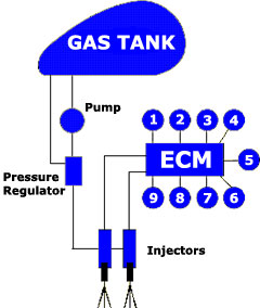 So now, your motor is running, and you blissfully head on down the road, never having to bother sitting there playing with the choke like the carb guys, or playing with it for a mile or so down the road until the motor will idle on it’s own. Great stuff! So now, your motor is running, and you blissfully head on down the road, never having to bother sitting there playing with the choke like the carb guys, or playing with it for a mile or so down the road until the motor will idle on it’s own. Great stuff! Now that the motor is warmed up, the ECU is going to use the VE, AFR, and Spark Advance Tables. What is the VE (Volumetric Efficiency) table? This is actually a percentage of how much air is flowing through a running motor, versus its theoretical capacity. So now we have got to use some theory. Let’s take an 88 cubic inch motor running at 5600 RPM at Wide Open Throttle (WOT); this motor would have a theoretical airflow capacity, or VE of 100%, when it is flowing 143 cubic feet per minute (CFM). If the same motor flowed 107 CFM at 5600 RPM and WOT, it would have a VE of about 75%. Conversely, it the motor was equipped with some high performance airflow mods, like pipes, air cleaner, cams, and the like, and flowed more than 143 CFM at that 5600 RPM and WOT; it would have a VE of MORE than 100%. This is why you have to do adjust the ECU Maps when you put on pipes, air cleaner, etc. as the stock ECU doesn’t know about this extra stuff, and you’ll be running too lean. There are VE tables for both front and rear cylinders, and Spark Advance tables for both cylinders. So, when you crack that throttle open, the VE tables tell the ECU how much air is flowing into the motor, while the Intake Air Temp. (IAT) and MAP sensors tell the ECU roughly what the air density is, so that the AFR (Air/Fuel Ratio) table can tell the ECM what Air Fuel Ratio should be required at that instant. (Hang in there!) Working along with everybody else, the Front and Rear Spark Advance Tables are also telling the ECU the advance required for that specific load. Happens real fast too. Let’s do that again, just to clarify it all one more time. With the motor running, a typical sequence of events follows: 1. The ECU (or ECM) is constantly monitoring the Crank Position Sensor, Throttle Position and Intake Air Temp., which tell it RPM, Intake Air Temperature, and Manifold absolute pressure(MAP). 2. The ECU will then look at the VE tables using throttle position and RPM, and it now knows the volume of air that should be going through the motor, at this exact moment. 3. At the same time #2 above is happening, the ECU takes a glance at IntakeAir Temp. and MAP and calculates the air density. Remember, that is how the ECU figures out how much oxygen is in the air entering the motor.
4. Now, armed with all the above wonderful knowledge, the ECU can go directly to the AFR (Air/Fuel Ratio) table, knowing exactly how much oxygen is coming into each cylinder, and sends the correct pulse width to the injectors to achieve the AFR it has been programmed (mapped) to achieve at that particular moment, based on load and RPM. 5. Don’t forget the Spark Advance Tables, as the ECU looks at these at the same time, and, for the same conditions, sends the coil the appropriate timing signal for front and rear cylinders. Clear as mud, right? Only one more thing to mention, and we’re done. (For now) The last thing on the agenda to talk about is the “Heat Management System” incorporated in the Harley ESPFI systems. This system is used to control excessive heat, and operates in three “Phases.” In Phase 1, if the ECM sees engine temperature above 300 degrees F., while the bike is either moving, or standing still, it will reduce idle speed. Theory being that a lower idle has less sparks, producing less heat. In Phase 2, if the ECM sees an engine temperature that is still climbing from Phase 1, it will richen up the AFR. Richer mixture has a cooling affect. In Phase 3, if the ECM sees that the temperature is still going up, and the bike is sitting still, it will go ahead and skip-pulse the injectors, not delivering fuel on each intake stroke. Again limiting combustion and producing less heat. Phase 3 is only active when the bike is sitting still. These 3 Phases pass from one to another without pause, and you may not even feel or notice it. Article courtesy of American Iron Magazine . |
Harley Fuel Injection